Community Post: BobDaRedDino’s Case Mods – Part 1
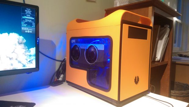
This is a two part community post by member Bobdareddino aka Lucas. He has a swagged out Bitfenix Prodigy and we wanted him to highlight some of the case mods he has done on this tiny beast of a case.
A lot of you have seen my BitFenix Prodigy bro cave by now, including all the mods I’ve jammed into my case. They’ve been a lot of fun to design and make, and the final product is great to look at. One of the reasons why I picked the Prodigy is because it’s so moddable. There’s a lot you can do to this case with just a screwdriver.
RBG LEDS
We’ll start with the most unique mod I’ve done: the color LED strip. This project has gone through a few different revisions since inception. First, I started off with three knobs and a switch on what used to be the cover for the 5.25” drive slot. Each knob is on a potentiometer, which outputs a voltage between 0 volts and 12 volts based on its position. From there, I wired it to a connector to go to the PSU and the signals to an Arduino Uno, which is basically a tiny computer with I/O ports for reading and writing values. The Arduino reads each incoming voltage as a color, then outputs an equivalent digital signal to each of three transistors. By rapidly switching each transistor on and off, the Arduino flashes each color very rapidly, which the eye sees as a smooth blend of colors. This process is called pulse-width modulation, or PWM. For example, having red on 100% of the time, green on 15%, and blue off all the time makes orange. At that point it was just a matter of getting it all in the case.

The Arduino in its case with the transistors attached (the black and silver things at the tip of the pliers)

All in and ready to go! You can see the back of the control panel (top left), the Arduino in its case (middle left), and a bit of the LED strip, which wraps around the top of the case (top middle)
As nice as this design was, it didn’t last very long because I thought it was messy. Time for version 2.0! I decided to remove the Arduino. By doing this I would be adjusting the voltage drop across each color instead of using PWM. This way, if the red knob was at 50%, the red LEDs would get 6 volts. The problem is that this creates a lot of heat. To cool it off, I milled a block of aluminum into a heat sink, put a bit of thermal paste on the back of each potentiometer and screwed it onto the panel.
After a few months the knobs became an eyesore and I got bored of just a solid color. I came up with an all-digital solution, bringing back the Arduino for version 3.0. I wrote a GUI program in C# to control the Arduino over a USB connection. With this I added the ability to fade between colors to provide some variety. That code is all available on GitHub, if you’re interested. Once inside my case, the new setup looked like this:
Which became this after some Legos got involved:

The orange-blue fade I usually have running. The colors and timing are adjustable from the program. (Click to see animated gif!)
Thanks for reading Part 1! Part 2 will be out soon with all the details on the case window and case panel mods.


